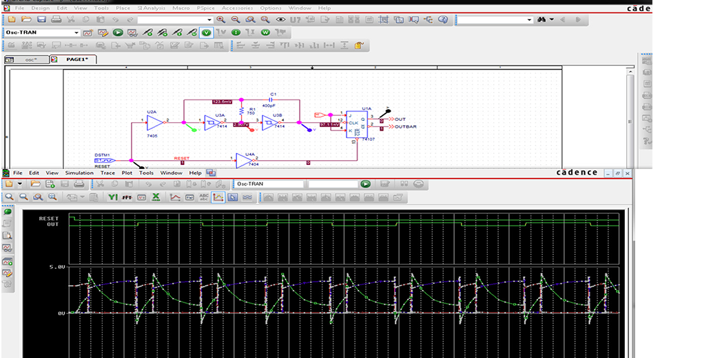
Pspice Program For Schmitt Trigger
This is an analysis of the emitter-coupled Schmitt trigger circuit of Probs. 10.75 and 10.76 in Bobrow (see Fig. A rising and falling 5V ramp is coupled to. This is an analysis of the emitter-coupled Schmitt trigger circuit of Probs. 10.75 and 10.76 in Bobrow (see Fig. A rising and falling 5V ramp is coupled to. Non inverting schmitt trigger using op amp pdf Schmitt Trigger Circuit Using. For use as. Sony Ericsson J20i Flash File here. Comparator and Schmidt Trigger. Schmitt trigger using op amp pspice.

One of the various Schmitt Trigger configuations. The input is a triangle vawe, with a 20V peak to peak voltage, the Op Amp supply is 15V and the saturation output voltage is 14V. The Op Amp saturates when V + reaches 7V, beacause of the simmetric divider (R 1=R 2) To plot the hysteresis loop by PSpice: - go to the plot window - cancel all traces except V out - double click the x axis (a label.) - in the 'X Axis' tab, in the 'Axis settings' window, click the 'Axis Variable.' Button - choose V in then 'OK' and 'OK' again. Vray Cho 3ds Max 8.